
Mission critical, oil and gas communications network in the desert: Case Study

The Challenge
A well-known Multi-National Oil and Gas company had problems with the reliability of their existing wireless communications network in one of their larger installations in the Middle East, and they sought a more reliable and higher performance solution.
The solution would have to provide a mission critical network for use in the desert.
They approached Case Communications and listed a number of key criteria that the network had to provide:
24 x 7 x 365 in desert conditions (this meant no fans or moving parts)
The equipment had to operate from -400C to +700C
In the event of failure service must be restored in less than 3 seconds.
To operate at 1Gbps and to support voice, data and video
Fully managed to allow total control and performance monitoring.
Any RTU must be able to connect to any point in the network without any changes.
Oil and Gas Communications Network – The Solution
Case Communications discussed these requirements with the customer and it was decided that the Case Communications IFE 8T 2GB-MXE Industrial switches using ‘X-Ring’ technology would be ideally suited to the application.
In order to allow any RTU to work anywhere it will be necessary to build a ‘Flat’ layer two network, but at the same time with so many devices on the network and with the addition of voice and video traffic it will also be necessary to divide the sub-networks by use of VLANS.
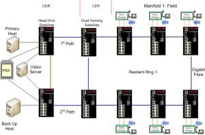
Industrial Ethernet Ring Network for Wellheads Operating Over Single Mode Fibre Optic Cable.
Each Wellhead typically consists of 6 to 8 Wellheads which are connected in a ring topology using Single Mode Fibre. Each RTU cabinet is supplied with a Case Communications DIN rail mounted patch panel and Case IFE-8T-2GB-MXE Switches providing the Ring Technology. In the event any switch failing or a fibre break the Ring will selfheal in approximately 30 milli-seconds.
Each switch has ports 1 and 2 allocated for the RTU and ports 7 and 8 for voice and video respectively which go into their own VLAN to keep the traffic separate from the RTU and other traffic.
Each two rings share Head-End switches which then attach VLAN tags to all traffic flowing out of the ring, thereby allowing the RTUs to be moved dynamically and to become members of the VLAN they were physically attached to.
The diagram below provides an overview of a typical ring network as used on each manifold.
Here we can see each ‘Well Head’ fitted with a Case Communications IFE-8T2GB MXE Rugged Gigabit Ring switch and a DIN rail mounted Fibre optic patch panel.
Industrial Ethernet ring technology
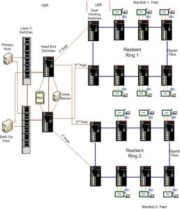
Two X-Ring Networks Sharing Dual Head End Switches
In order to expand the network to an infinite size without too much traffic going to each sub-network Case Communications used Layer 3 switches to keep each two manifolds on one VLAN..
As can be seen in the diagram below we have two manifold rings each with their own ‘dual homing’ switches, if either of the ‘Dual Homing’ switches fail the other switch will take over within a few milli-seconds.
VLAN tags are assigned by the dual homing switches allowing any RTU to be installed anywhere in the network and to instantly become part of that manifolds VLAN. This allows the flexibility required while keeping traffic segmentation.
Industrial Ethernet Ring technlogy using dual homing
Simplified Overview Network
The first phase of the network was installed in 2011 and consisted of two large rings, shortly followed by a further eight rings each with 8 switches.
A number of additional Rings were installed in 2012 with new Rings being added on an on-going basis.
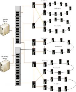
Multi industral Ethernet ring overview
Control and Management of the Network.
To manage, monitor and control the network a CaseView Network management system was supplied. This continually interrogates each network element and at the same time receives ‘traps’ from the network, allowing a database of events to be recorded. Network performance tools allow traffic levels to be monitored and in the event of a failure an instant alarm can be viewed and an SMS or e-mail sent to a network engineer
Summary
The new network is far more reliable than the original Wireless network and has several times greater capacity. This allows oil production to continue without interruption and has allowed new applications such as voice and video to be added to the network.
For more information please contact Case Communications.